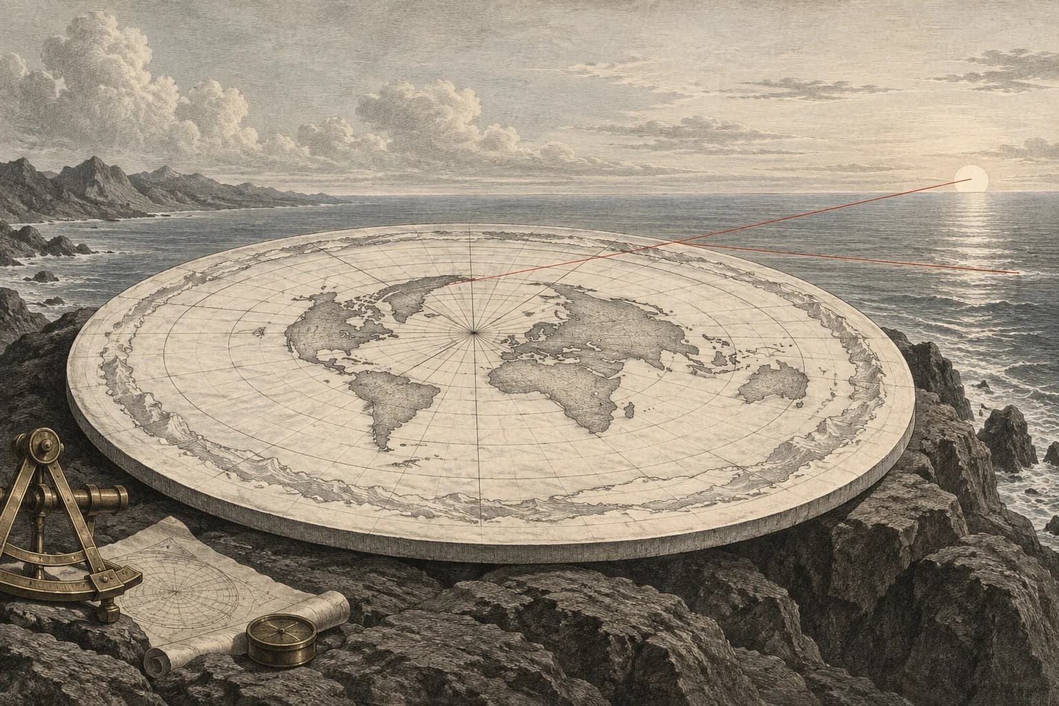
A circular shadow is assigned to a circular disk
The claim is that Earth’s curved eclipse shadow supports a flat disk just as well as a sphere. There is a sound point inside it: a disk facing a light source can produce a circular outline. A statement that only a sphere could ever cast a round shadow would be too strong.
The equivalence fails when it is extended to other orientations without examining them. A disk’s face and edge are different shapes to incoming light. A sphere presents the same silhouette as it turns. The alternative therefore needs to account for how Earth, the Sun and the Moon are arranged, rather than selecting whichever disk angle supplies a circle.
The eclipse is a moving sample of a larger shadow
A lunar eclipse occurs when the Moon passes through Earth’s shadow. In the umbra, Earth blocks direct sunlight from the full solar disk. In the surrounding penumbra, only part of the Sun is blocked. A partial lunar eclipse exposes an especially useful view of the boundary: a dark curved edge advances across a still-bright part of the Moon.
The curved outline was discussed in Aristotle’s argument for a spherical Earth long before spacecraft photographs existed. The important distinction in that argument is between the changing shapes of the ordinary lunar phases and the shadow boundary seen during an eclipse. Those are different arrangements of illumination, not interchangeable pictures of the same process.
The eclipsed Moon is also not simply painted black. Some sunlight passing through Earth’s atmosphere can reach it and change its colour and brightness. That optical behaviour concerns the light within and around the shadow. The geometric question here isolates the outline that an ideal opaque object presents to the incoming rays.
Give the disk its favourable angle, then tilt it
Start with an ideal thin circular disk under parallel rays, and observe its shadow on a plane perpendicular to those rays. Define tilt as the angle between the disk’s normal and the light direction. At zero tilt, the disk faces the source squarely. Its shadow is circular, so the control preset gives the disk exactly the favourable case that the claim requires.
As the disk tilts, one shadow diameter remains equal to the disk diameter. The perpendicular diameter becomes D cos θ. The ratio of the short diameter to the long one is therefore cos θ, regardless of the disk’s size. This is a projection calculation; it uses an adjustable example disk and does not pretend that its diameter is a measurement of Earth.
With the opening assumptions of a 100-centimetre disk and a 60-degree tilt, the shadow is 100 centimetres wide and 50 centimetres high. Its short-to-long ratio is 0.50. A sphere of the same diameter keeps a circular silhouette in this parallel-ray comparison. Changing the diameter scales the disk shadow but cannot repair its axis ratio.
The instrument leaves the tilt under your control because a real alternative model would have to predict it from the celestial arrangement. It does not fit an ellipse to a particular eclipse photograph. The finite size of the Sun and Earth’s atmosphere require additional geometry for detailed eclipse boundaries; they do not grant a thin disk the rotational symmetry of a sphere.
How round is a tilted disk’s shadow?
An ideal thin disk receives parallel light. Tilt is measured from face-on illumination, and the shadow is measured on a plane perpendicular to the light rays.
A circle has ratio one. Tilting the disk drives this ratio downward.
The tilted direction contracts by the cosine of the selected angle.
The diameter perpendicular to the tilt remains unchanged.
Working tape
- Radians per degree
3.141593 ÷ 180 = 0.017453 - Tilt in radians
60 × 0.017453 = 1.047198 - Cosine of the tilt
cos(1.047198) = 0.5 - Uncompressed shadow diameter
100 × 1 = 100 - Disk diameter × cosine tilt
100 × 0.5 = 50 - Short diameter as a share of long diameter
0.5 × 100 = 50
One favourable orientation is not equivalent geometry
At the assumed 60-degree tilt, the example disk casts a shadow 100 centimetres wide and 50 centimetres high. Its short-to-long diameter ratio is 0.50. Enlarging the disk scales both dimensions together and leaves that ratio unchanged. Turn it face-on and the ratio returns to one: the disk can indeed cast a circle.
A sphere keeps a circular silhouette as its orientation changes. That symmetry explains the recurring curved eclipse boundary without requiring a flat face to be aimed toward the Sun each time. The disk’s circular shadow depends on its alignment, so a disk-based eclipse explanation must also account for the predicted orientation of its face.